


Description
Product image is representative only. Actual product may differ in appearance depending on size, configuration, and options selected at order.
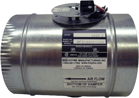
Inline duct flow switch that confirms positive airflow is occurring at the switch location — not just that the fan is running. Factory-mounted externally on a complete galvanized inline duct section. Installs like any inline fitting. Switch signal feeds the ADP relay adaptor or control system. Two voltage options: 24 Vac and 120 Vac. Sizes 4"–9".
✓ Responds to air velocity — not static pressure — in a pressurized zone or VAV duct, static pressure can be elevated while airflow through a branch is zero; the PFS paddle deflects only when air is actually moving past it with sufficient velocity
✓ Catches blocked-screen conditions a current sensor misses — fan runs at full current against an iced intake screen; current sensor reports normal; PFS reports no airflow; the ADP holds the appliance off
✓ External switch body — no electrical components in the air stream — only the paddle is inside the duct; no wiring, no contacts, no moisture-sensitive components in the airflow path
✓ Complete inline duct section — not a clip-on probe — factory assembly installs in the duct run with standard upstream and downstream duct connections; mounts vertically (upward) or horizontally
✓ Passive contact output — feeds ADP relay adaptor input, thermostat or ventilation controller digital input, or BAS point; select 24 Vac or 120 Vac to match the input circuit of the receiving device
Mounting orientation is vertical (upward) or horizontal only. The paddle element must be oriented correctly relative to airflow and gravity for reliable activation. Do not install at 45 degrees, inverted, or at other angles not specified. Also confirm a minimum 3–5 duct diameters of straight run upstream — do not install directly downstream of elbows or transitions where airflow is turbulent.
| What you need to confirm | Use | Limitation |
|---|---|---|
| Damper blade has physically reached open position | Damper end switch (SPO/SPC or SO2) | Does not confirm airflow — duct could still be blocked downstream |
| Actual airflow is occurring in the duct | PFS — this product | Does not confirm blade position — only that air is moving past the PFS location |
| Both blade position AND airflow confirmed | Damper end switch + PFS in sequence | Highest assurance — required on some combustion air code interpretations |
| Size | 24 Vac — Part Number | 120 Vac — Part Number |
|---|---|---|
| 4" | PFS-0400-024 | PFS-0400-120 |
| 5" | PFS-0500-024 | PFS-0500-120 |
| 6" | PFS-0600-024 | PFS-0600-120 |
| 7" | PFS-0700-024 | PFS-0700-120 |
| 8" | PFS-0800-024 | PFS-0800-120 |
| 9" | PFS-0900-024 | PFS-0900-120 |
Select size to match duct diameter. Select voltage to match the control circuit the switch signal feeds into. For sizes outside 4"–9" contact factory.
Confirms
Actual airflow — not fan motor current
Sizes
4"–9" standard
Voltage
24 Vac or 120 Vac
Activation
Air velocity — not static pressure
Switch Body
External — outside air stream
Mounting
Vertical (upward) or horizontal only
Where to install in the duct run: on combustion air applications, install downstream of the HOM or MOH — when the damper opens and air begins flowing, the PFS confirms actual flow before the ADP relay adaptor allows the appliance to fire. On fresh air applications, install downstream of the HAC or MAC. For sizes outside 4"–9" contact factory.
Galvanized inline duct section — external switch assembly
Made in Canada · No electrical components in the air stream