
Diagram #8C7: Forced Air Furnace having a replacement air supply duct together with an exhaust fan venting three bathrooms equipped with 24Vac Power Open control dampers.
HMI Hoyme Manufacturing Inc. Special Note: Circuits are colored for clarification only and are not necessarily those found in actual installations. Combustion Air Damper Wires, however, are colored as shown.
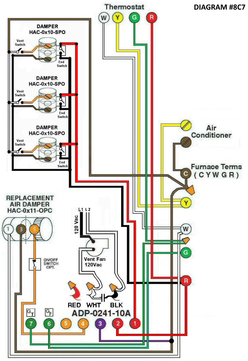
Diagram #8C7: Forced Air Furnace having a replacement air supply duct together with an exhaust fan venting three bathrooms equipped with 24Vac Power Open control dampers.
- Replacement Air Control Damper, Power Closed with built in relay(HAC-0x11-OPC);
- Damper(s) with End Switch (HAC-0x10-SPO) controlled with a 24Vac switches from each bathroom.
- 24Vac Relay Adaptor (ADP-0241-10A) to function as a control centre supplying 120Vac for an exhaust fan.
OPERATION:
- Furnace fires with thermostat signal and Replacement Air damper opens.
- Turn on Vent switch to any of the 24Vac dampers with end switch to simultaneously turn on Furnace Fan, opens Replacement Air Damper and supply 120Vac to the exhaust Fan.
- Optional Switch (i.e. toggle switch, de-humidistat) allows full control of Replacement Air damper to open as required.
N.B. Replacement Air Damper is not affected by the ‘Manual’ setting of the Furnace Fan or by the operation of an Air Conditioner.