
Timer, Vent Switch, Replacement Air Damper, Power Open and a 3-way Ventilation Switch:
#9B1. Same as #9B but uses a Power Open Fresh Air Damper (HAC-0x10-OPO)
HMI Hoyme Manufacturing Inc. Special Note: Circuits are colored for clarification only and are not necessarily those found in actual installations. Combustion Air Damper Wires, however, are colored as shown.
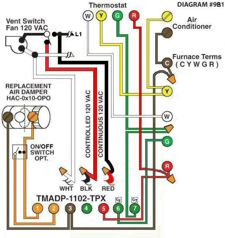
Diagram #9B1: Forced Air Furnace having a Replacement Air Supply Duct together with an Exhaust Fan controlled by a designated 3-way Ventilation Switch and/or an Interval Timer Adaptor.
- Replacement Air Damper, Power Open, (HAC-0x10-OPO)
- Ventilation Switch (3-way) supplies Controlld and Regular 120Vac (3-wires) to the Furnace area.
- Relay Adaptor with Interval Timer Adaptor (TMADP-1102-TPX) functions as a control center
OPERATION:
- Furnace fires with Thermostat signal
- A Three-way Ventilation Switch in one position allows the normal function of the Timer Adaptor to turn on the Ventilation Fan, open the Replacement Air Damper and turn on the Furnace Fan simultaneously. The Ventilation Switch in the other position, turns on the Ventilation Fan only (Not recommended unless living in coastal climates warmer than -10ºC and/or ample replacement air is supplied)
- Optional Switch (i.e. toggle switch, timer, de-humidistat) connected between #1 and #2 of the Adaptor allows full control of Replacement Air Damper to open as required
N.B. Replacement Air Damper is not affected by the ‘Manual’ setting of the Furnace Fan.